How to install the adjustable AST Smart ECO VCM Modules
The unit needs to be installed into a cold engine so you do not trip a P0128 or P0118 code and get a check engine light.
Most engines will take 4+ hours to fully cool down to ambient temperature after being operated normally.
If you have an ODB2 scanner and can reset error codes, you do not need to wait for the engine to fully cool down.
Please let us know if you have any questions before or during installation.
All of our items are 100% tested and inspected prior to shipping to ensure their function and durability.
Please feel free to contact us directly at [email protected], or 209-353-3330.
STEP 1: FAMILIARIZE YOURSELF WITH YOUR AST SMART ECO VCM MODULE
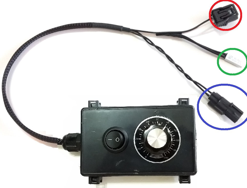
Your AST Smart ECO VCM module may look different than below, but they all require a similar installation procedure.
The female plug [red circle] will plug into the white connector in your engine.
The male plug [blue circle] will plug into the existing female plug you just removed from ECT1 in the previous step.
The thermal switch [green circle] will sense the engine temperature and automatically engage the Smart ECO VCM module.
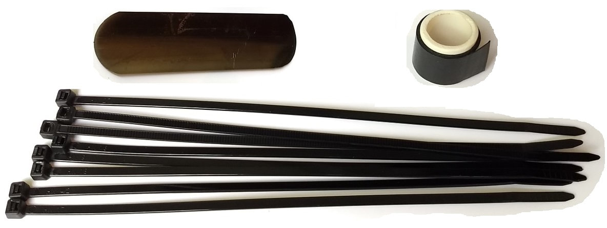
The unit also comes with other mounting hardware, including some tie down straps, a metal band, and thermal tape.
Depending on what model you order, your mounting hardware may look different than shown below.
Depending on what model you order, your mounting hardware may look different than shown below.
STEP 2: REMOVE EXISTING PLUG
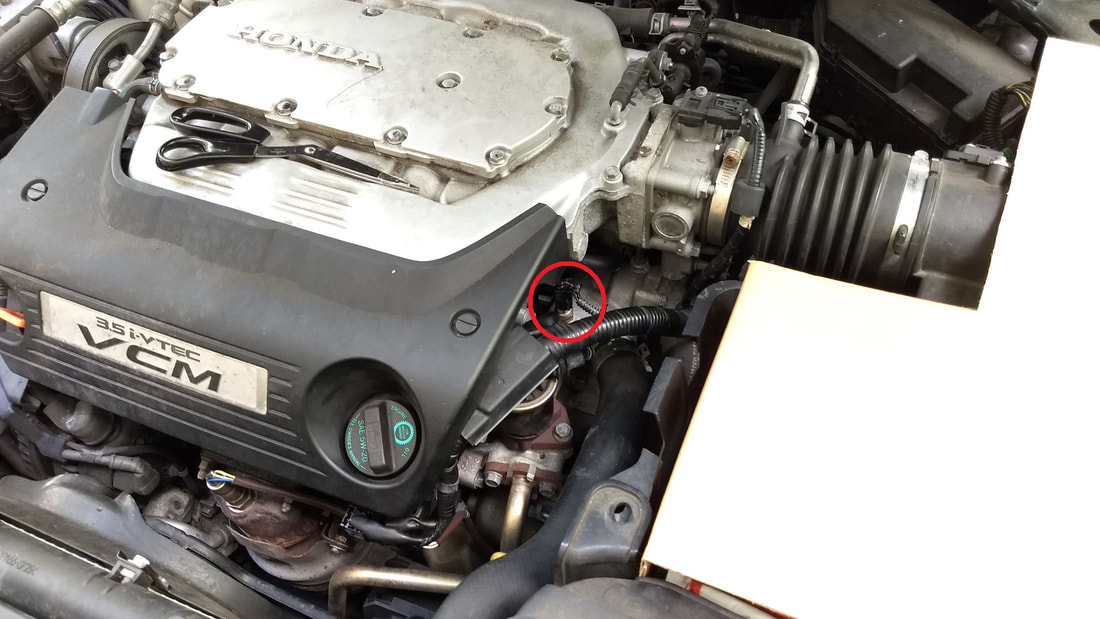
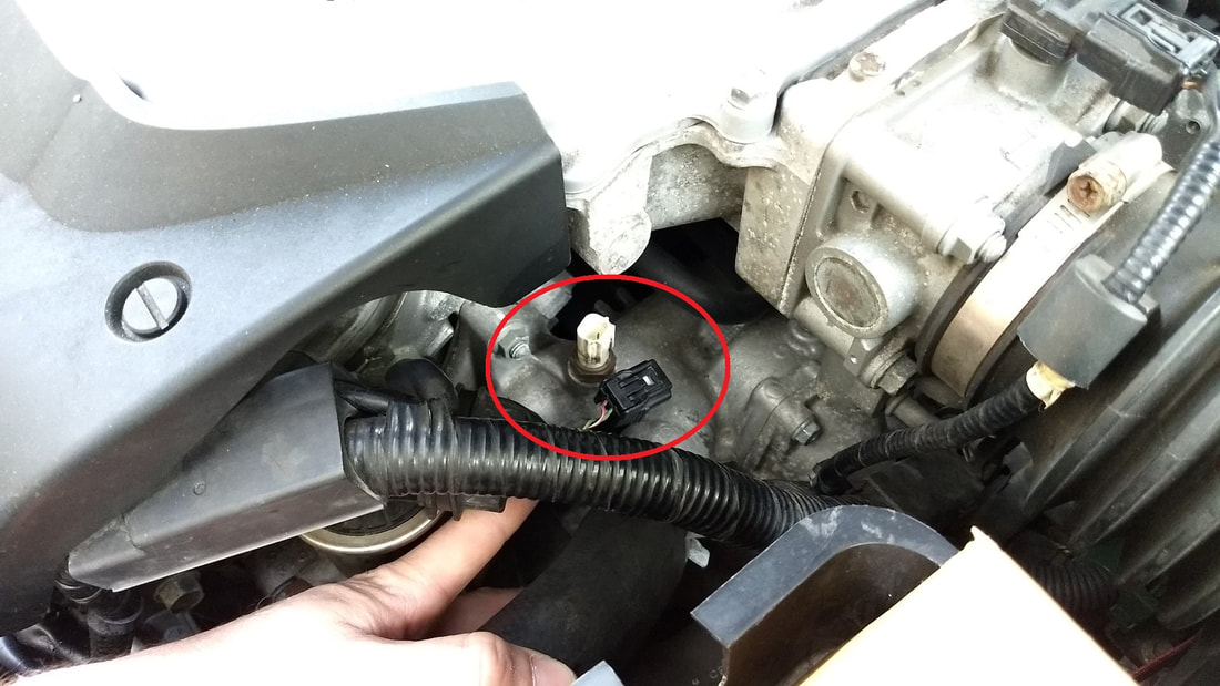
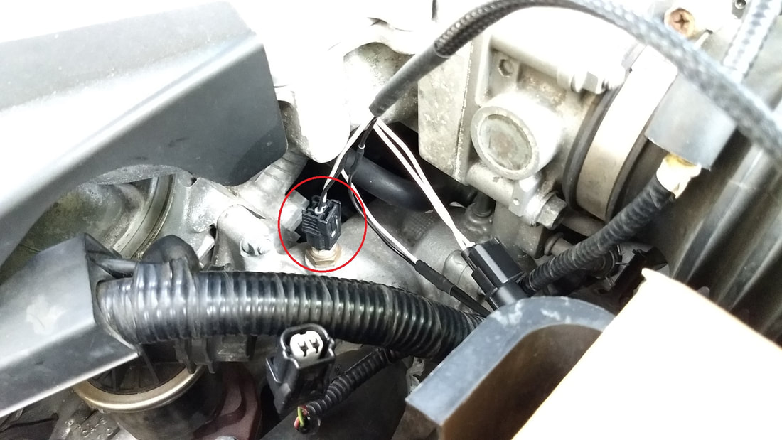
The plug has a locking mechanism on one side, push in with your thumb to unlock it, then carefully slide it up to remove the female plug from the ECT1 sensor. Make sure your engine is cold so you do not burn your hands or trip any check engine lights.
The plug has a locking mechanism on one side, push in with your thumb to unlock it, then carefully slide it up to remove the female plug from the ECT1 sensor. Make sure your engine is cold so you do not burn your hands or trip any check engine lights.
STEP 3: PLUG IN FEMALE CONNECTOR, THEN PLUG IN MALE CONNECTOR
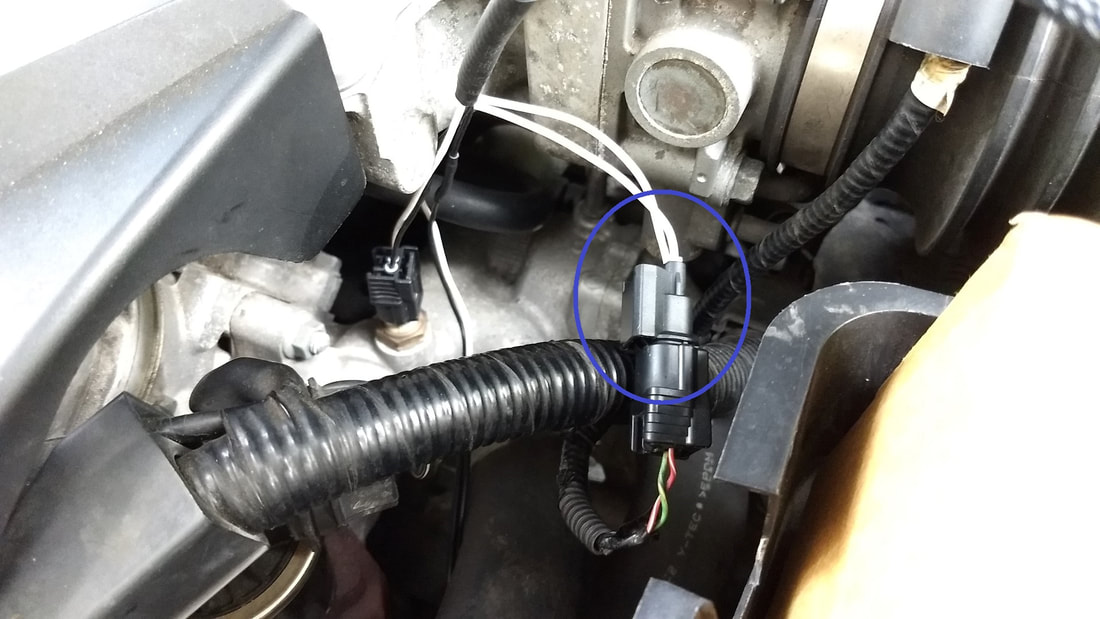
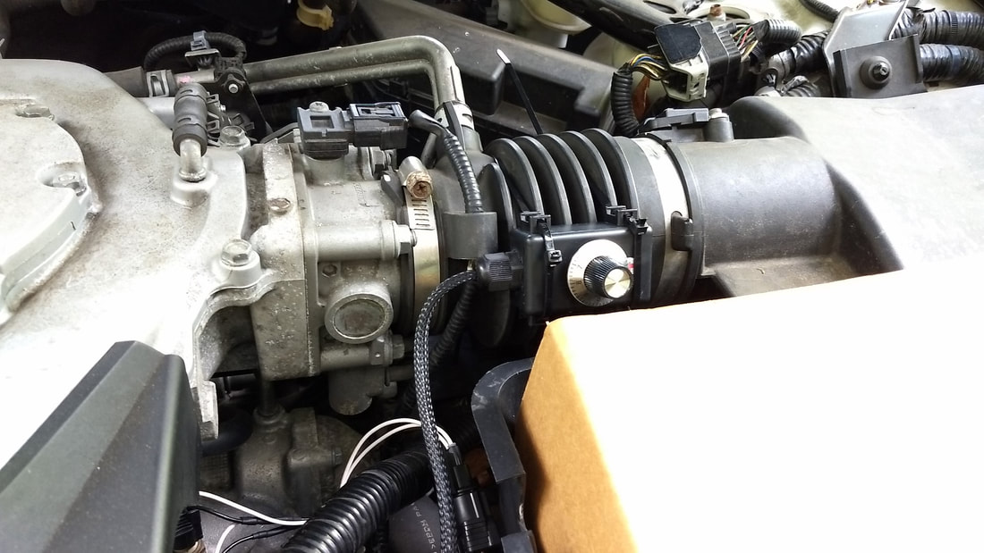
Plug the one end of the AST Smart ECO module into the white connector on the engine. [1ST PHOTO]
You should hear it click into place when it is fully inserted.
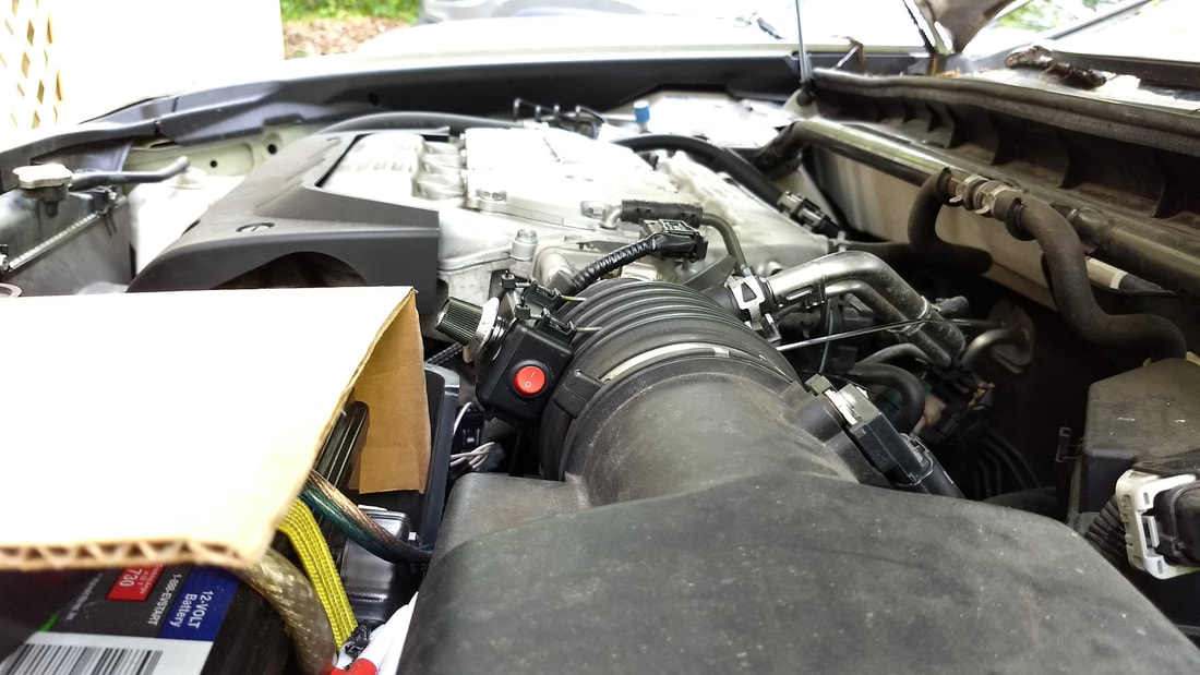
Plug the other side of the AST Smart ECO VCM module into the plug you removed from the engine. [2ND PHOTO]
You should also hear it click into place when it is fully inserted.
THERMAL SWITCH NOTES:
The thermal switch senses the heat from the engine and will automatically engage the AST Smart ECO VCM module when your engine has warmed up. Their are two suggested places to mount the thermal switch.
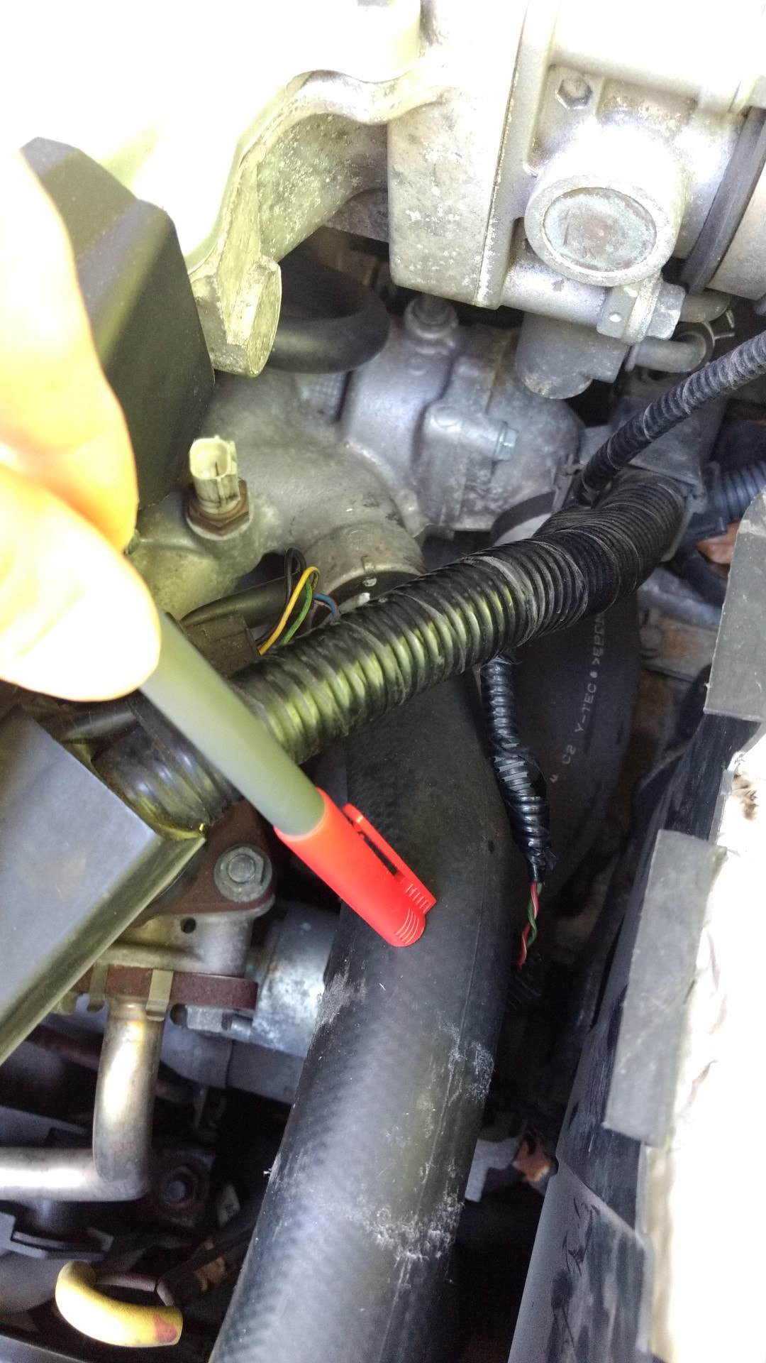
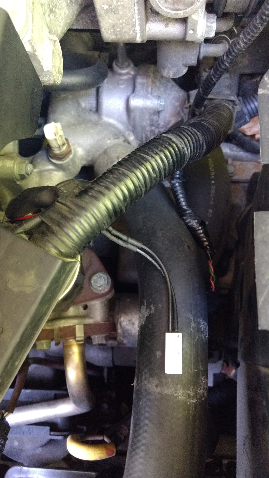
The first suggested location is for most locations / climates and is directly tied to the radiator hose as shown in the first photo below.
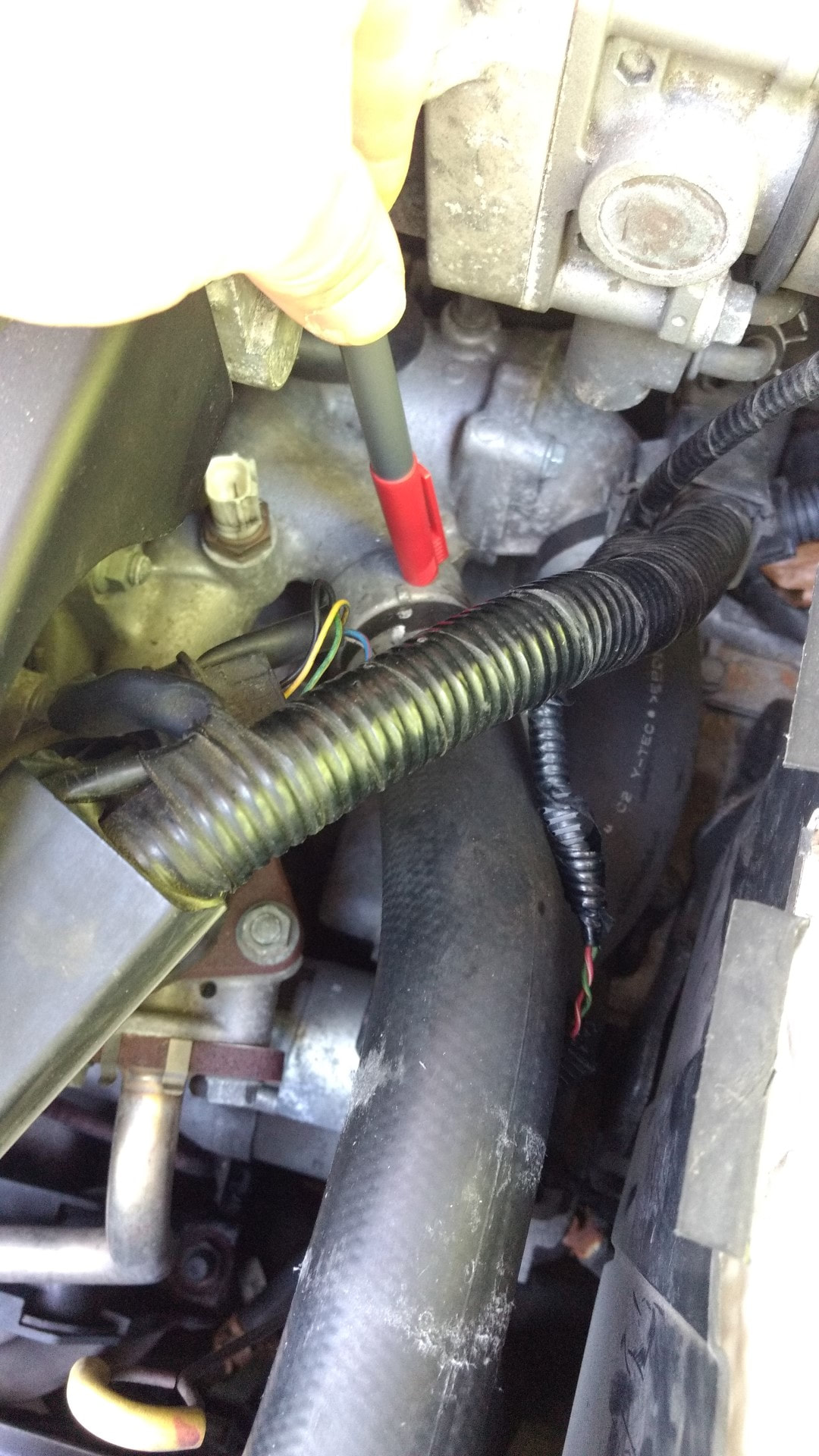
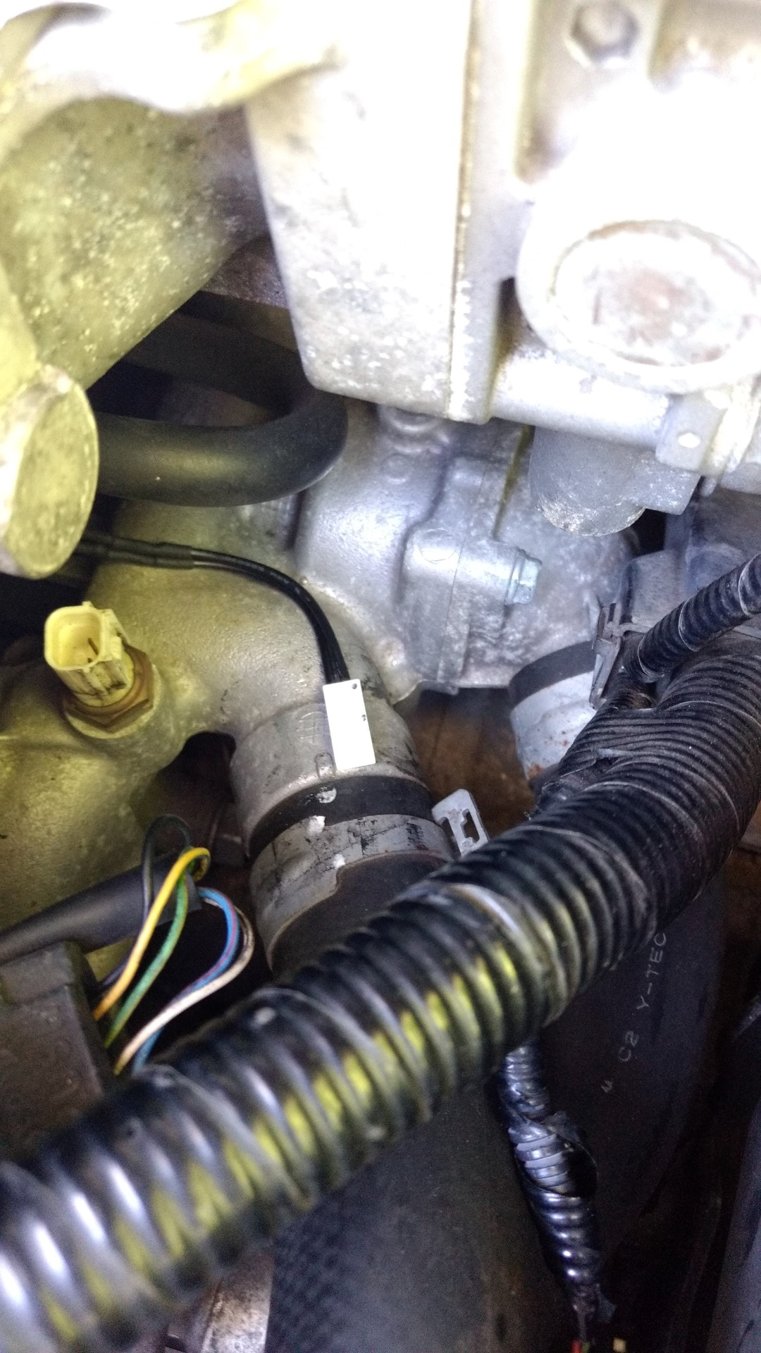
The second suggested location is recommend for mainly colder climates [with temperature rarely above 80F], and is tied to the coolant pipe as shown in the second photo below.
The different locations will affect how fast the unit turns on. When mounted to the metal pipe, the unit will turn on faster because it will sense the heat from the engine quicker.
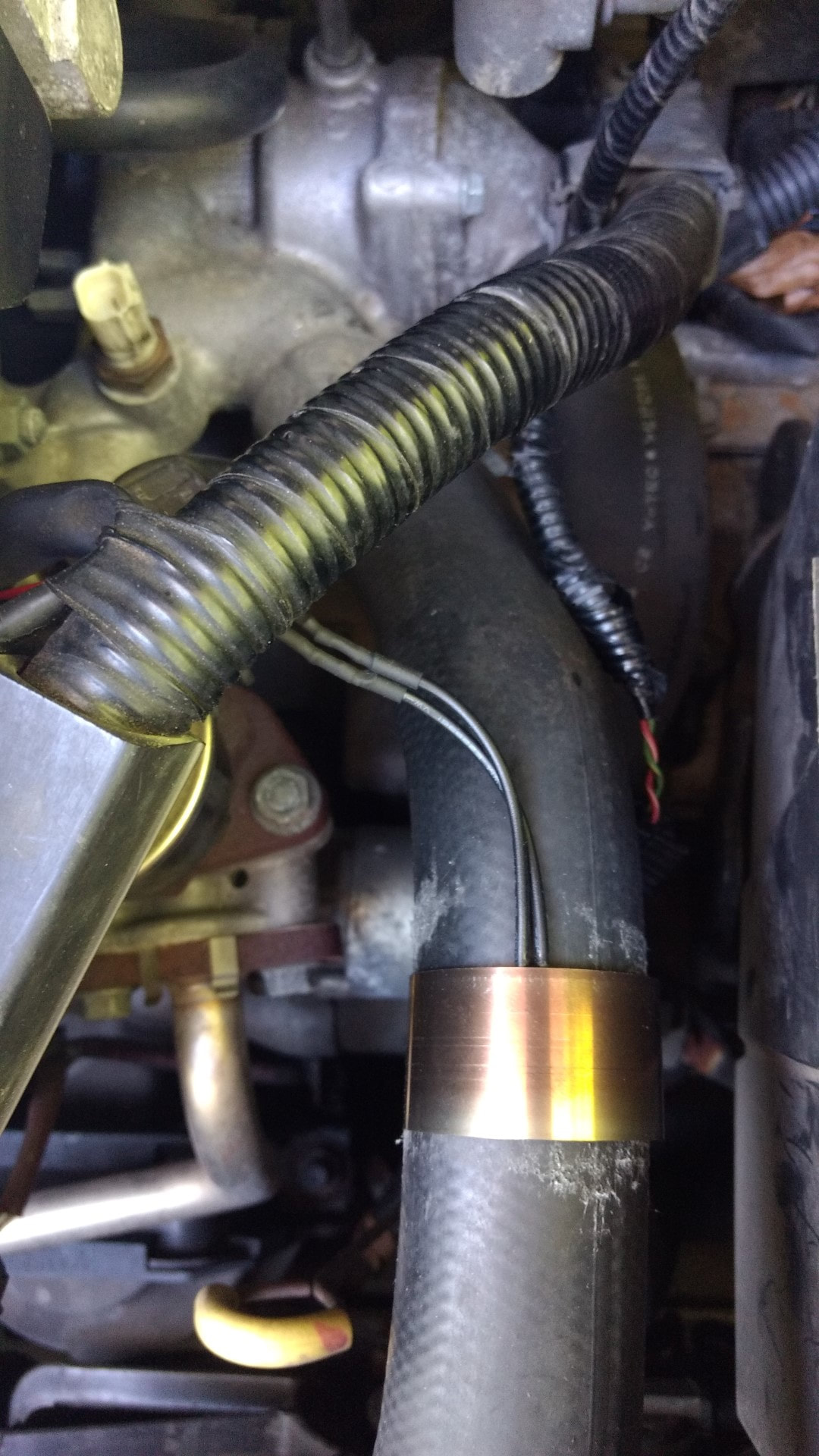
If you are unsure which location to use, try mounting to the rubber hose first. Hold in place with the metal compression band while testing. Once you are happy with the function of the unit, you can cover with the insulating tape.
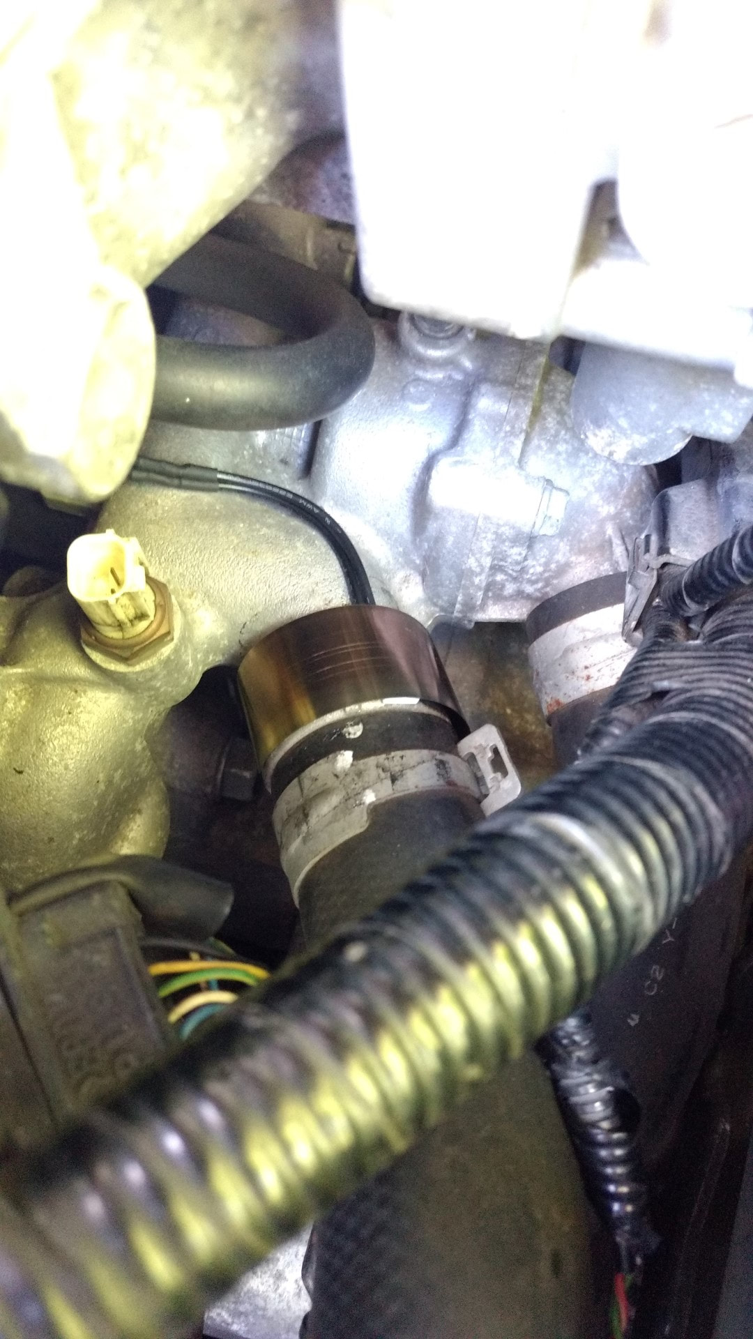
STEP 4: SECURE THERMAL SWITCH TO YOUR VEHICLE [RADIATOR HOSE MOUNTING LOCATION SHOWN]
This location works well for the majority of vehicles and installations.
Lay the thermal switch flat against your radiator hose.
Hold it secure with the insulating compression band. The band will quickly snap into place, so be careful when installing.
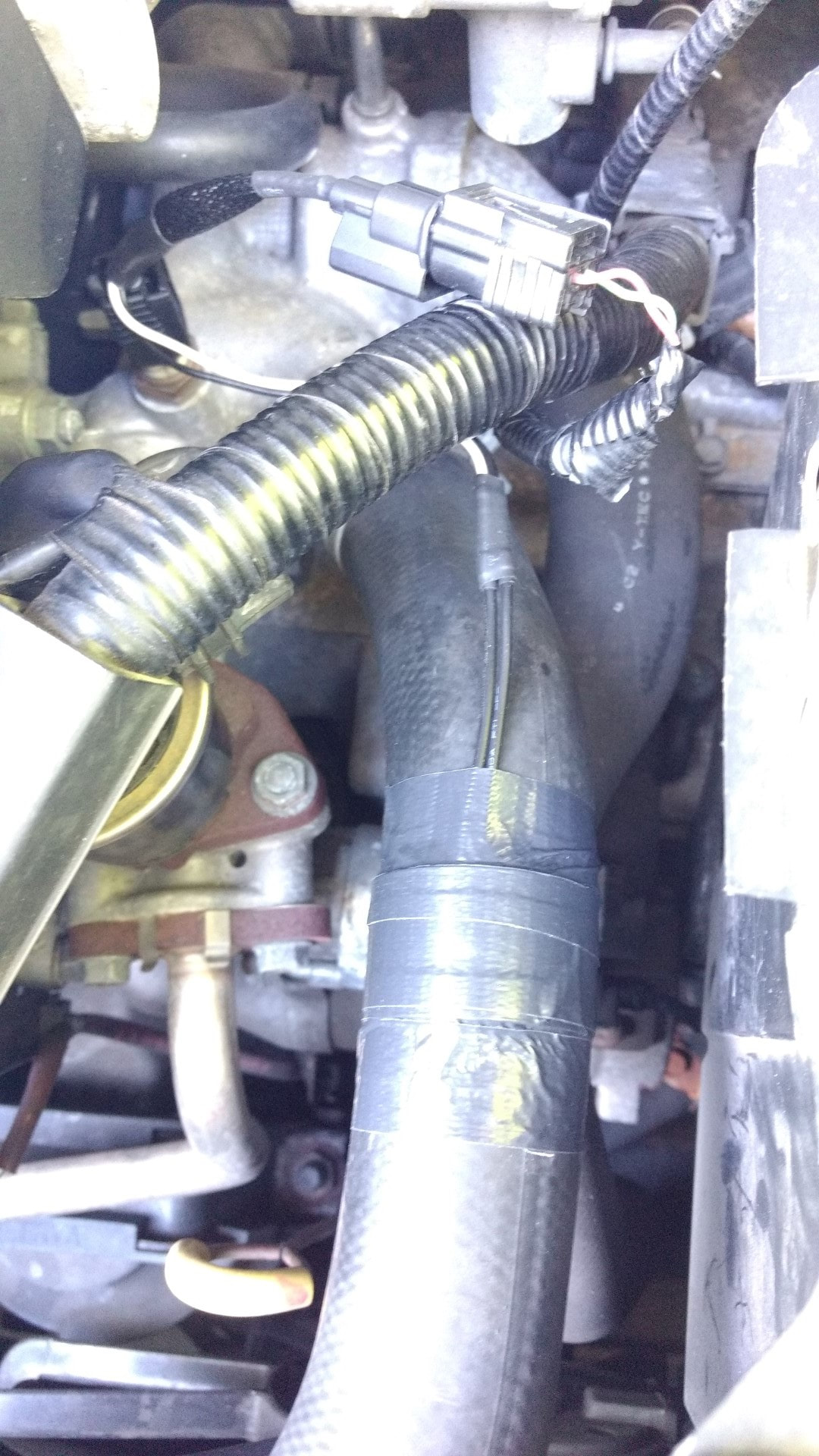
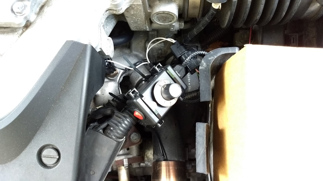
Cover with the thermal tape once testing and calibration is complete [3rd photo]
STEP 4 [ALTERNATE]: SECURE THERMAL SWITCH TO YOUR VEHICLE [COOLANT PIPE INSTALLATION]
Lay the thermal switch flat against your coolant pipe.
Hold it secure with the insulating compression band. The band will quickly snap into place, so be careful when installing.
Cover with the thermal tape once testing and calibration is complete [not shown]
Lay the thermal switch flat against your coolant pipe.
Hold it secure with the insulating compression band. The band will quickly snap into place, so be careful when installing.
Cover with the thermal tape once testing and calibration is complete [not shown]
STEP 5: SECURE ANY LOOSE WIRES AND MOUNT THE CONTROLLER MODULE
Your module may look different than the one below, but the installation procedure is similar.
Their are two suggested locations to mount the controller module.
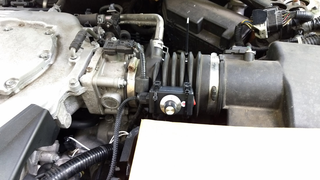
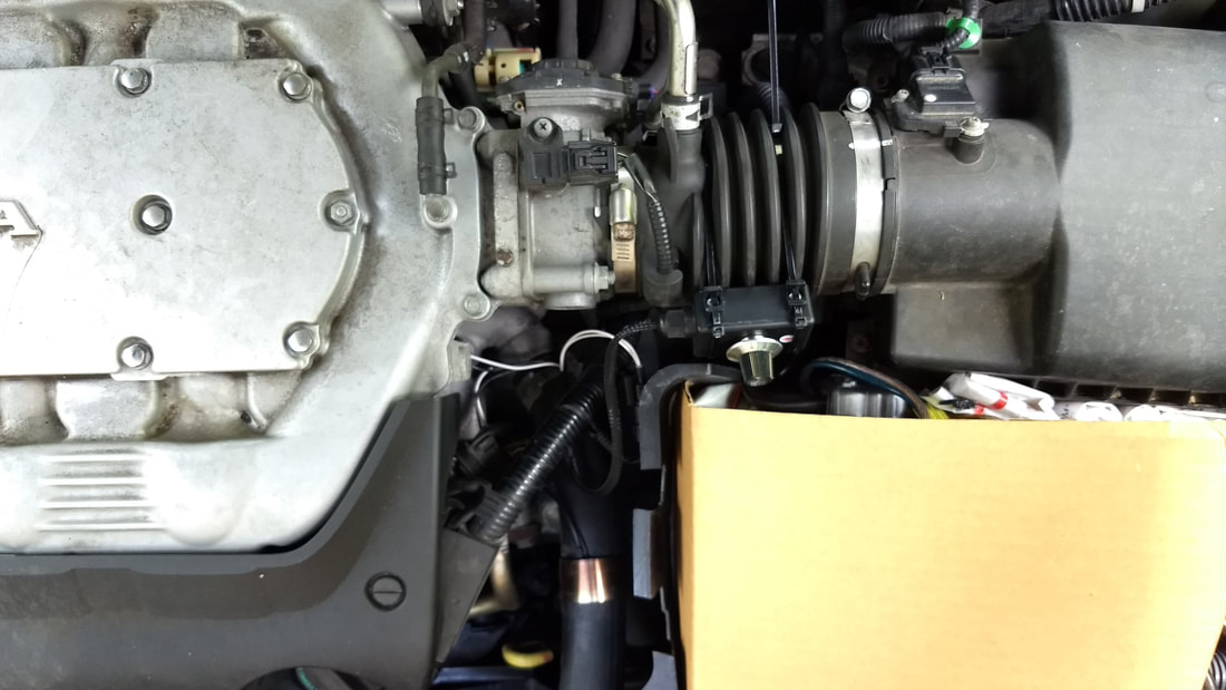
The first location is to the air intake hose. The second location is directly above the radiator coolant hose.
You can put the module in other locations, but please make sure it is not mounted directly to the engine or anywhere it will get very hot.
AIR INTAKE HOSE MOUNTING LOCATION:
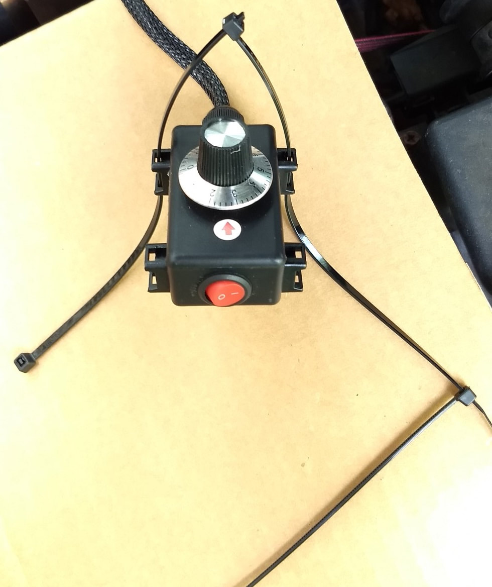
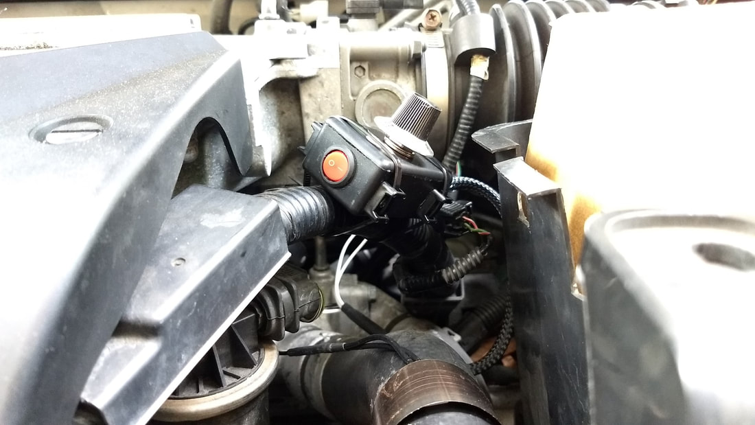
Use three zip ties and install over one side of the module as shown below. Do the same to the other side of the module.
Use three zip ties and install over one side of the module as shown below. Do the same to the other side of the module.
ABOVE RADIATOR COOLANT HOSE MOUNTING LOCATION:
Use two zip ties and install over one side of the module. Do the same to the other side of the module.
Use two zip ties and install over one side of the module. Do the same to the other side of the module.
INSTALLATION IS COMPLETE!
Now it is time to calibrate the module to your car, see below.
Now it is time to calibrate the module to your car, see below.
TUNING AND CALIBRATION OF YOUR AST SMART ECO VCM MODULE
The goal is to adjust the AST Smart ECO VCM module high enough to remove the ECO under a normal operating environment.
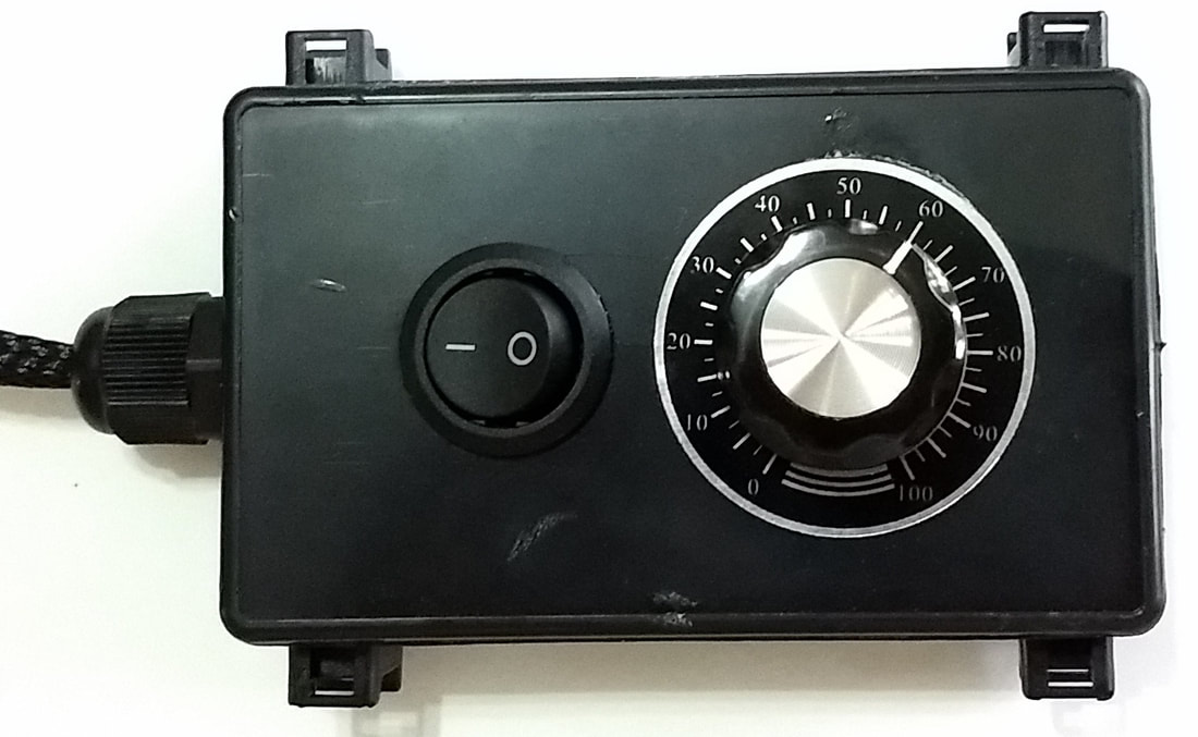
1. Disengage the white thermal switch by setting the black switch on the module to side '0' so it is pushed in, then adjust the rotary dial to #0.
2. Let your engine warm up / idle for about 15-20 minutes. Take note of where the engine temperature is on the dashboard. Generally it will be halfway up, in the middle.
3. Slowly adjust the rotary dial up to #60. You should notice the engine temperature display on the dashboard has dropped slightly.
4. Drive normally for about 5 minutes. If the ECO light is still coming on, adjust the dial up 10 to #70. Drive normally for another 5 minutes and continue to adjust the dial up half settings until you no longer see the ECO light turning on.
Most cars respond to settings below #90, with settings between #60 or #80 being the most common.
NOTE: The HIGHER the dial setting the LOWER the engine temperature and the less likely ECO will come on.
7. Once you are are happy with the dial setting, engage the white thermal switch by pushing the black switch on the module to side '1' so it is pushed in.
How the automatic activation works:
Under normal operation, the white thermal switch will automatically turn the module on when the engine has reached the proper temperature. When you first start the car for the day the engine and white thermal switch will be cold, so the AST Smart ECO VCM Module will NOT be active. Once your engine starts warming up and your radiator coolant starts flowing through the system, it will start to warm up the white thermal switch that you mounted to the vehicle. The white thermal switch will NOT engage the module until the engine coolant has reached approximately 160-175F. This may take 5-10 minutes of driving depending on your driving style, radiator efficiency and outside air temperature. If you live in south Florida, your engine will reach 175F a lot faster than if you lived in Canada.
The white thermal switch is designed to delay the activation of the module. This means when your car is first started and warming up, their may be a short time when ECO will be on. This is normal. If the module was active immediately when the car was started with a cold engine, you would likely get a check engine light with a P0118 warning code telling you that your thermostat is not set properly.
If you feel the unit is taking too long to automatically activate you can move the white thermal switch to a different location or reattach it so it makes better contact with the radiator hose or engine.
The faster the white thermal switch receives heat from the engine, the faster it will automatically engage the module.
RECORDED DATA FROM A TYPICAL DRIVE:
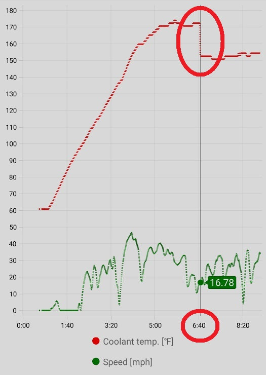
The graph below shows a typical unit in operation, reflecting data I collected from my ODB2 scanner and smartphone.
The engine temperature was approximately 63F when first started. This was also the air temperature outside.
I backed down my driveway and left the car to idle for approximately 1 minute, as I had to run back into the house to grab a couple of things for the road :) [I almost forgot my coffee!]
I then proceeded to leave my development and drive on some 25, 35 and 40 mph roads.
The engine temperature slowly increased until about 172F.
At that point, their was enough heat to transfer over to the AST Smart ECO VCM modules thermal switch and activate the unit.
The ECT1 reported engine temperature dropped by approximately 20 degrees to 152F.
While the engine temperature was being reported below 167F, the ECO mode was disabled.
Their was a small window from 5 minutes to 6:40 where the ECO mode was engaging, however the delayed activation of the AST Smart ECO VCM module is what sets it apart from the competitors - it automatically activates when the engine has warmed up, helping to prevent P0118 and P0128 check engine lights that other, "always on" units experience.

