How to install the Single Value AST Smart ECO VCM Modules
The unit should be installed into a cold engine so you do not trip a P0128 or P0118 code and get a check engine light.
Most engines will take 4+ hours to fully cool down to ambient temperature after being operated normally.
Most engines will take 4+ hours to fully cool down to ambient temperature after being operated normally.
STEP 1: FAMILIARIZE YOURSELF WITH THE ENGINE BAY
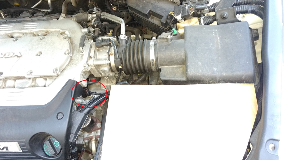
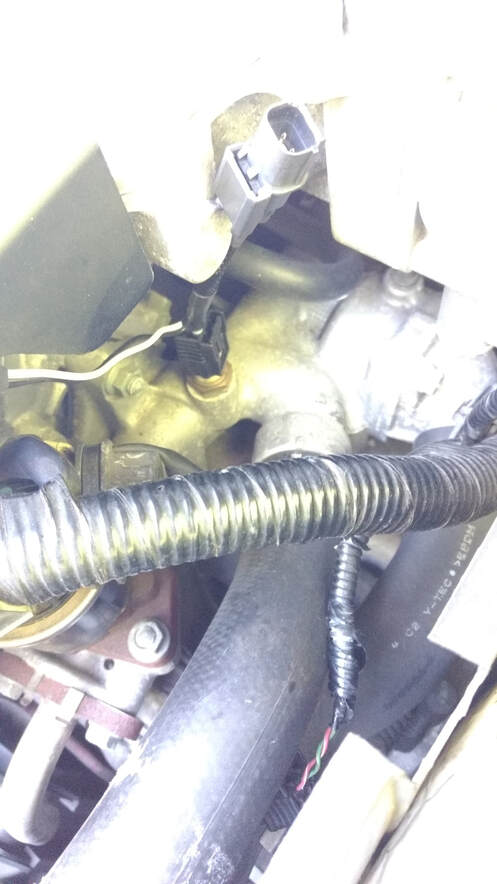
Locate your current ECT1 plug, normally located here. This photo is from a 2008 Honda Accord.
Locate your current ECT1 plug, normally located here. This photo is from a 2008 Honda Accord.
STEP 2: REMOVE EXISTING PLUG
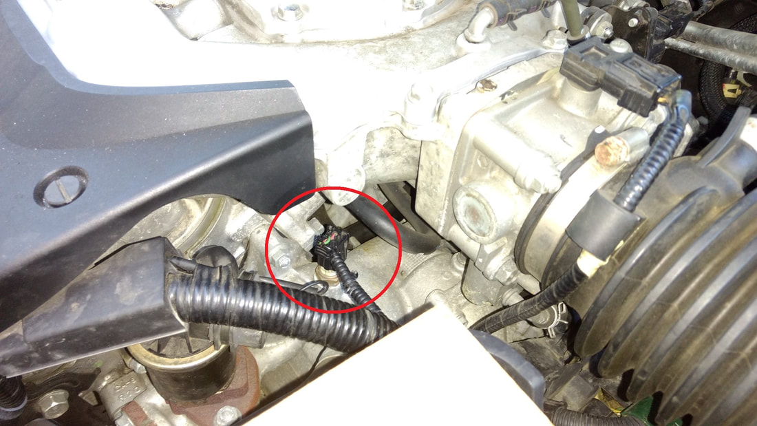
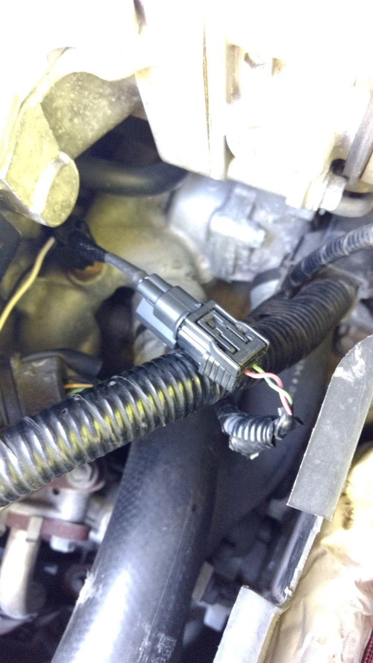
The plug has a locking mechanism on one side, push in with your thumb to unlock it, then carefully slide it up to remove the female plug from the ECT1 sensor. Make sure your engine is cold before performing this step.
The plug has a locking mechanism on one side, push in with your thumb to unlock it, then carefully slide it up to remove the female plug from the ECT1 sensor. Make sure your engine is cold before performing this step.
STEP 2: (CONTINUED)
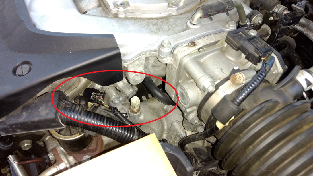
In the photo below, you can see the female plug fully removed from the ECT1 sensor.
In the photo below, you can see the female plug fully removed from the ECT1 sensor.
GENERAL NOTES:
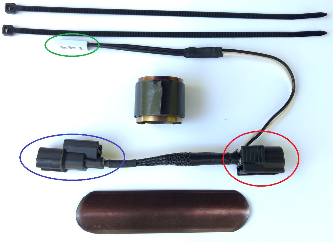
Your AST Smart ECO VCM module may look different than below, but they all require a similar installation procedure.
The female plug [red circle] will plug into the white connector in your engine.
The male plug [blue circle] will plug into the existing female plug you just removed from ECT1 in the previous step.
The thermal switch [green circle] will sense the engine temperature and engage the Smart ECO VCM module.
The unit also comes with other mounting hardware, including some tie down straps, a metal band, and thermal tape.
Depending on what model you order, your mounting hardware may look different than shown below.
STEP 3: PLUG IN FEMALE CONNECTOR, THEN PLUG IN MALE CONNECTOR
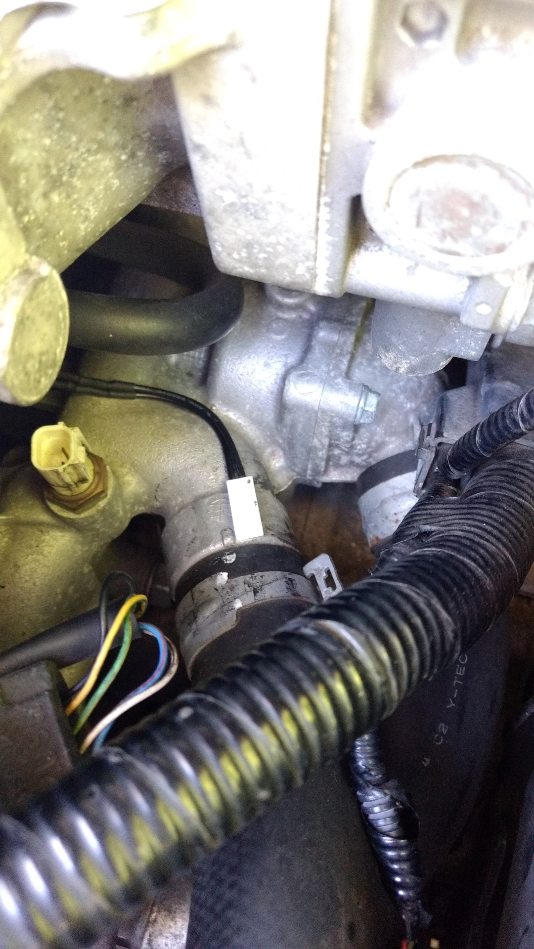
Plug the one end of the AST Smart ECO module into the white connector on the engine.
You should hear it click into place when it is fully inserted.
Plug the other side of the AST Smart ECO VCM module into the plug you removed from the engine.
You should also hear it click into place when it is fully inserted.
THERMAL SWITCH NOTES:
The thermal switch senses the heat from the engine and will engage the AST Smart ECO VCM module when your engine has warmed up. Their are two suggested places to mount the thermal switch.
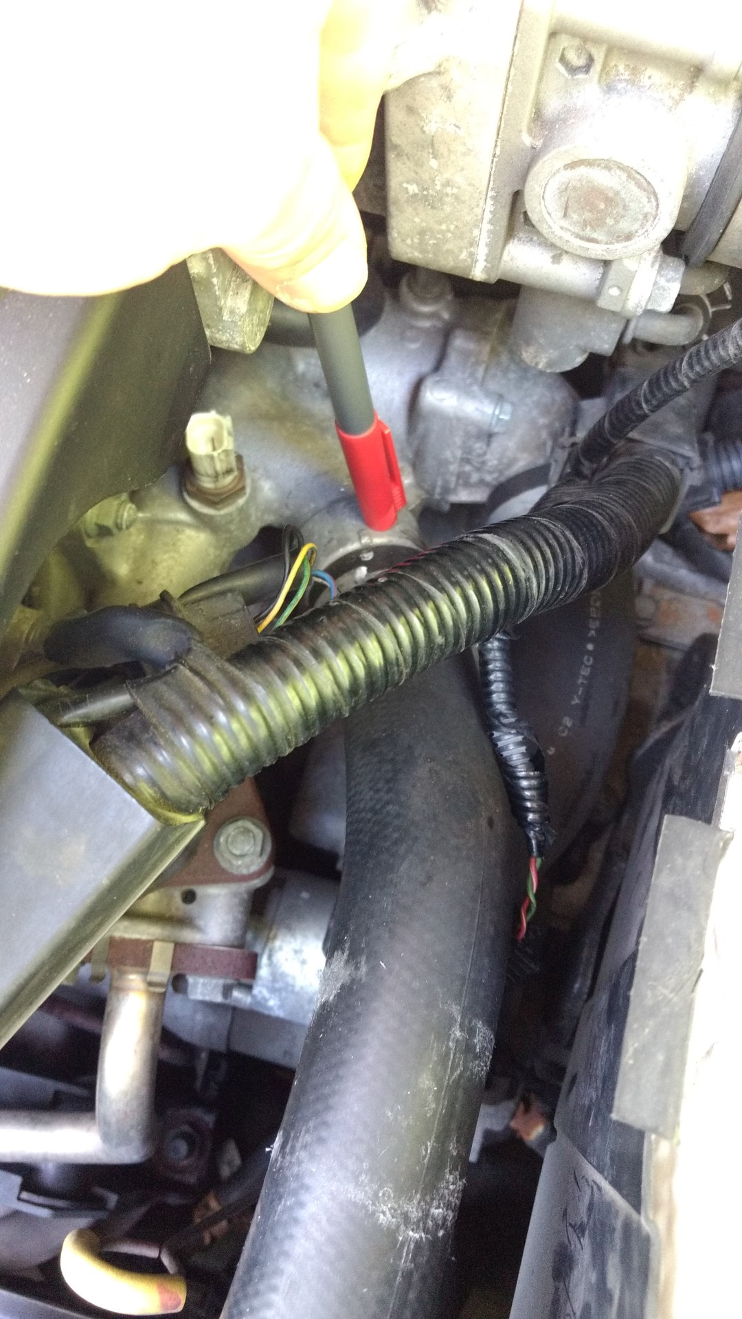
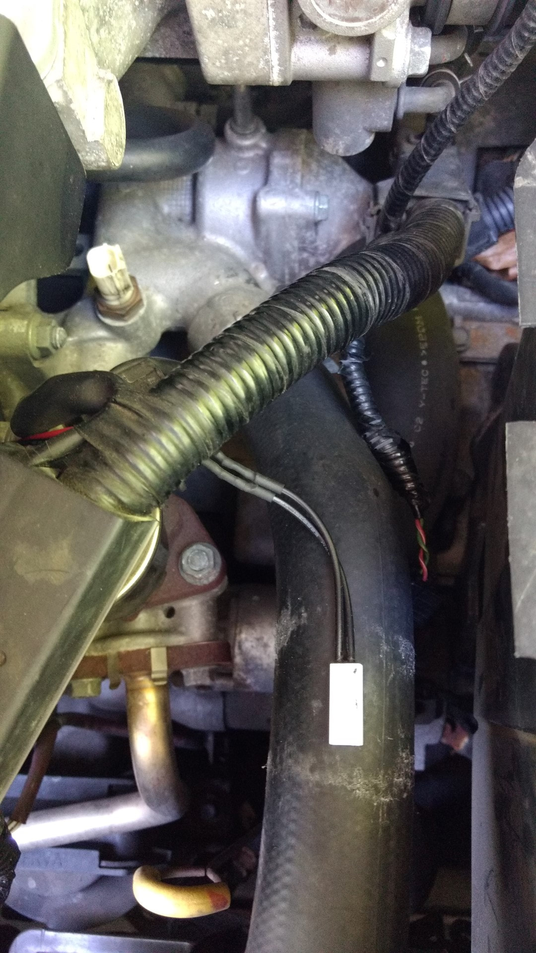
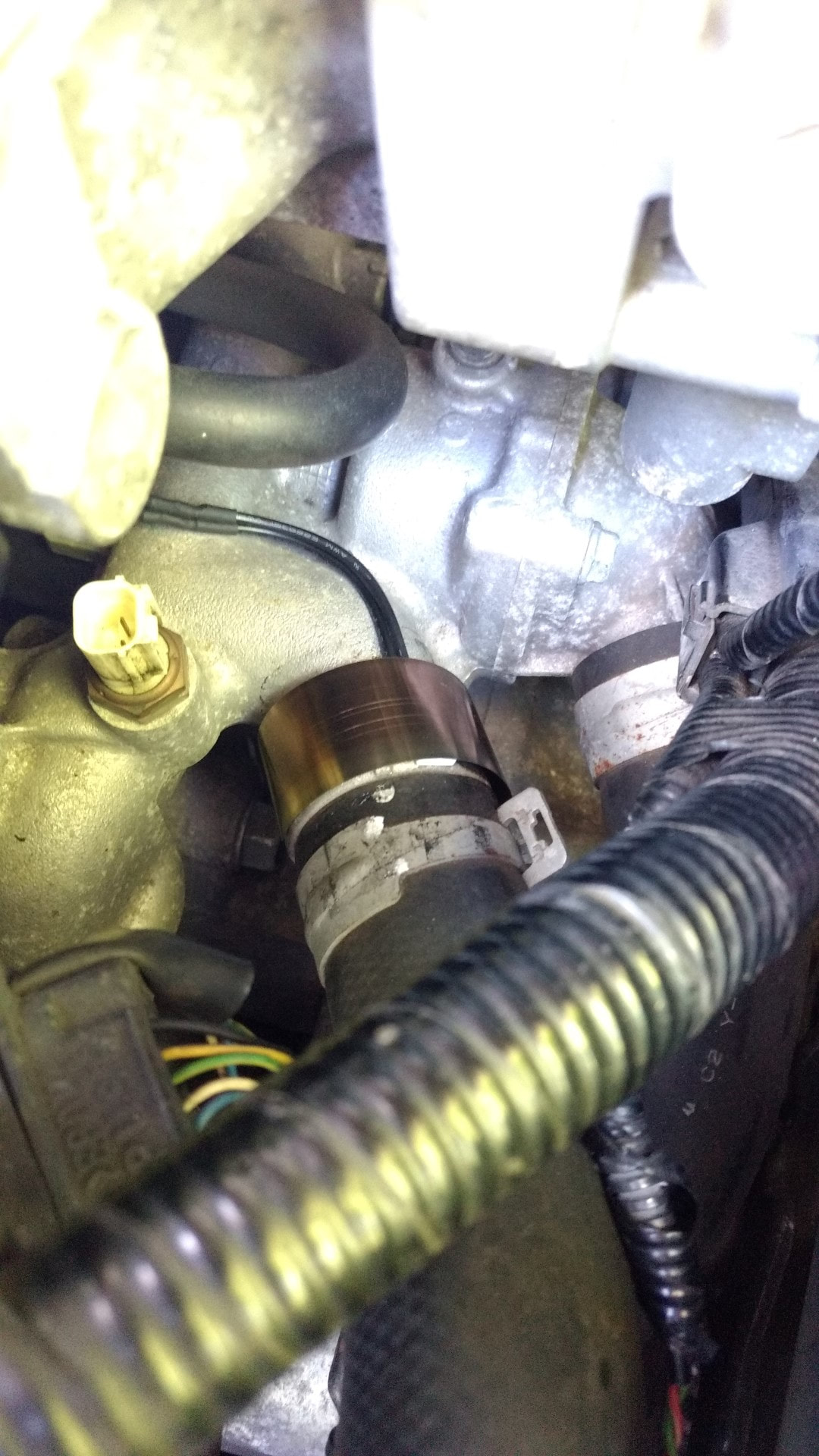
The first suggested location is for mainly colder climates [temperature rarely above 80F], and is tied to the coolant pipe as shown in the first photo below.
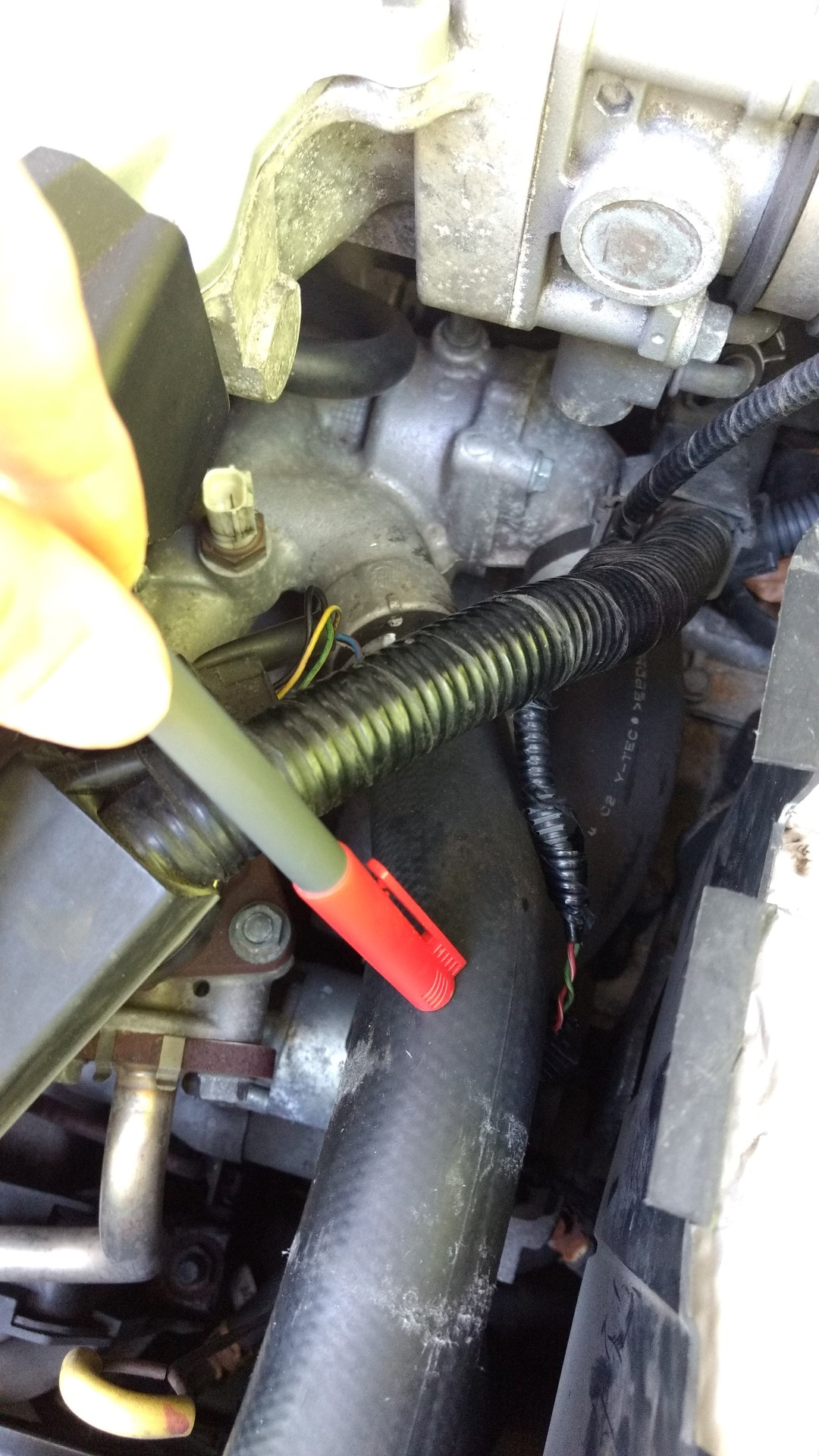
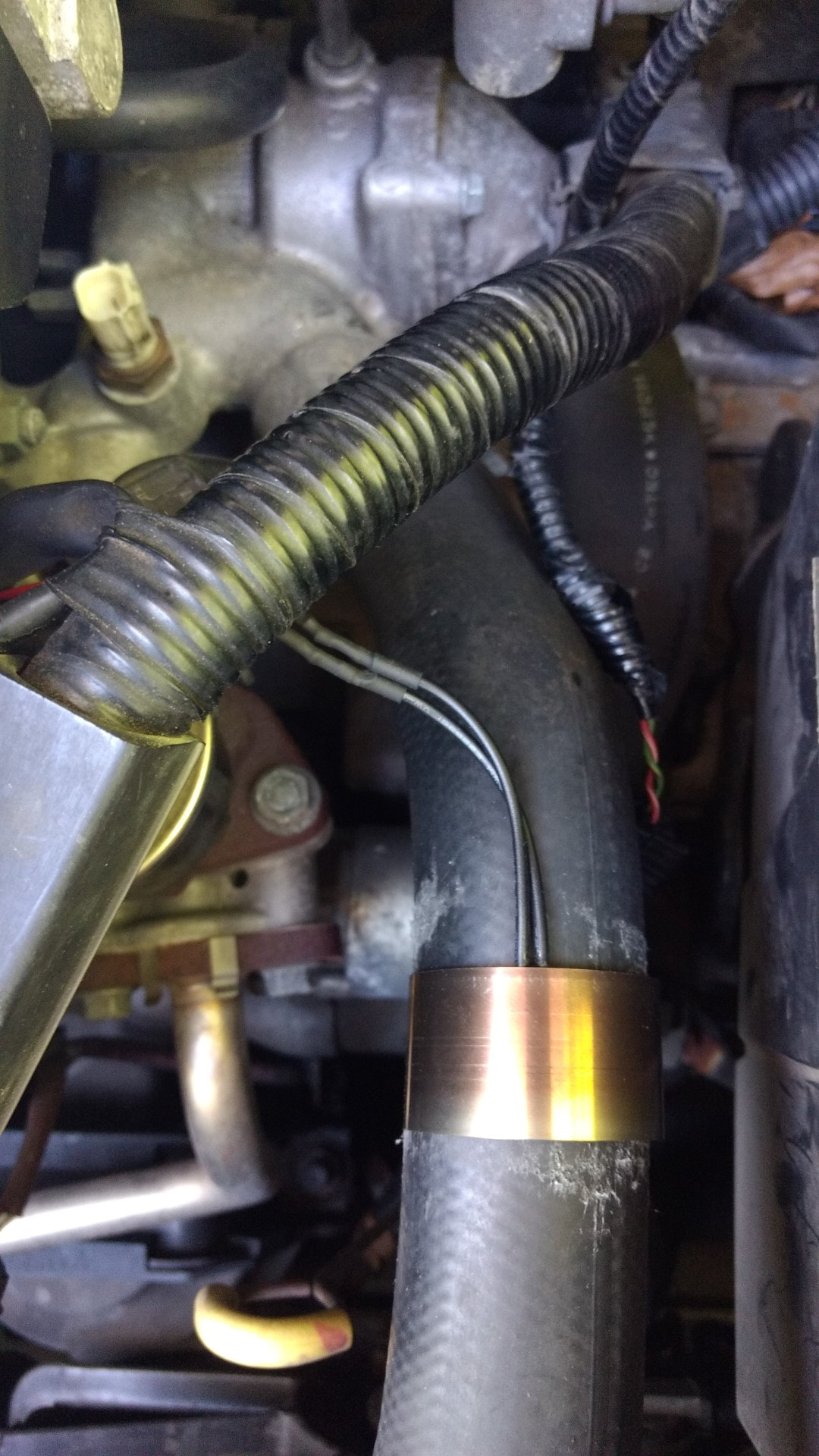
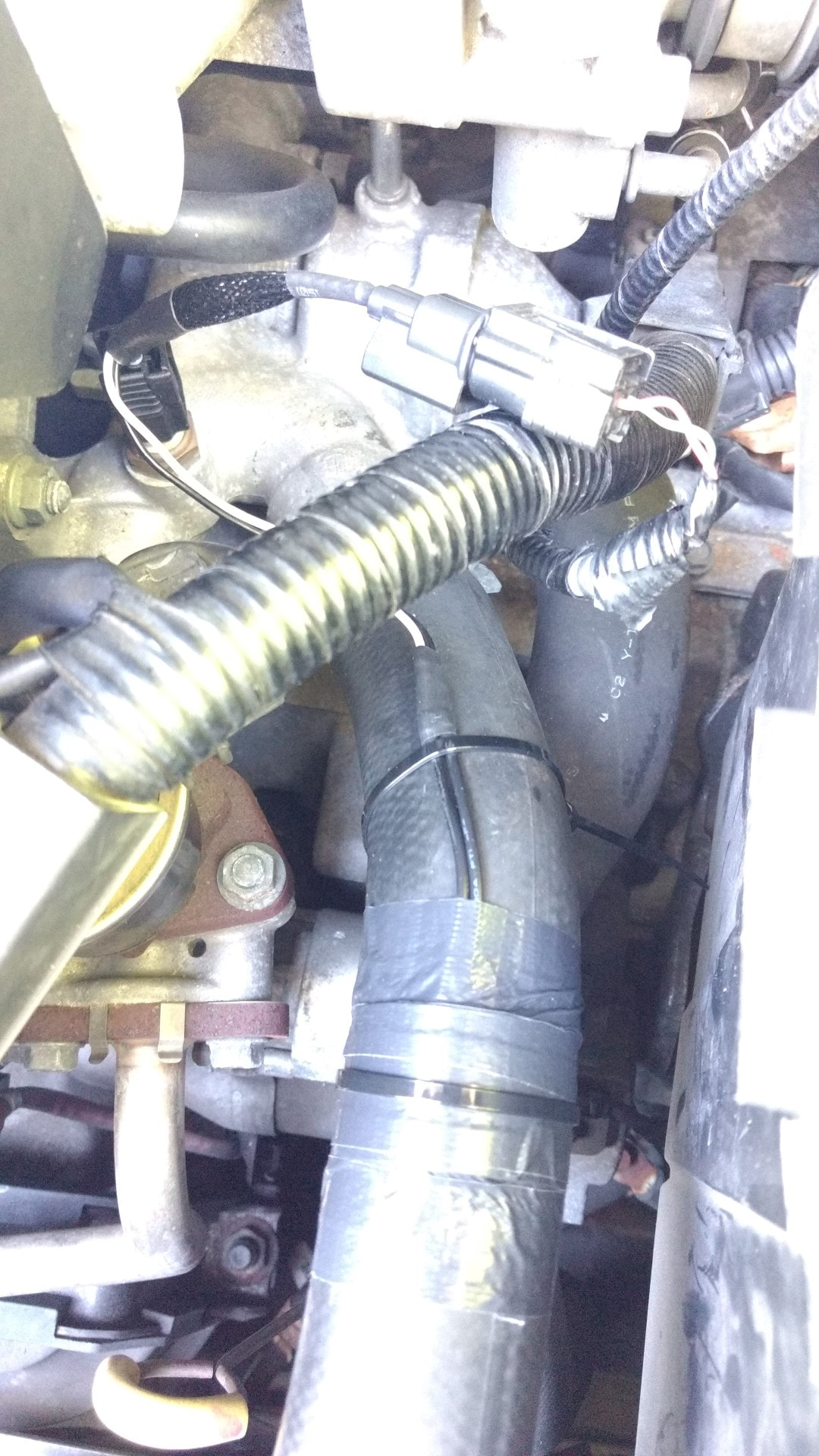
The second suggested location is recommend for everyone else and is tied to the radiator hose as shown in the second photo below.
The different locations will affect how fast the unit turns on. When mounted to the metal pipe, the unit will turn on faster because it will sense the heat from the engine quicker.
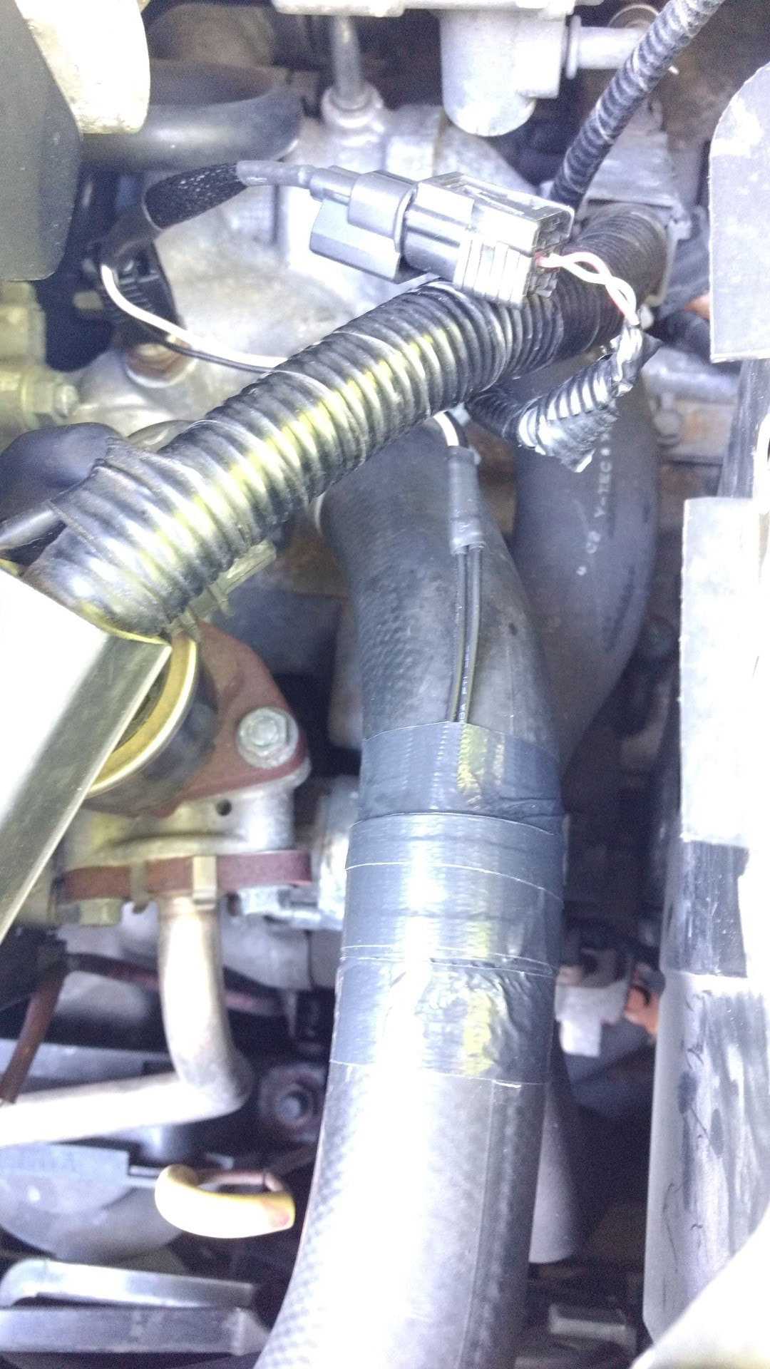
If you are unsure which location to use, try mounting to the rubber hose first. Hold in place with the metal compression band while testing. Once you are happy with the function of the unit, you can cover with the insulating tape.
STEP 4: SECURE THERMAL SWITCH TO YOUR VEHICLE [RADIATOR HOSE MOUNTING LOCATION SHOWN]
This location works well for the majority of vehicles and installations.
Lay the thermal switch flat against your radiator hose.
Hold it secure with the insulating compression band. The band will quickly snap into place, so be careful when installing.
Cover with the thermal tape once you are happy with the testing of this location [3rd photo]
STEP 4: SECURE THERMAL SWITCH TO YOUR VEHICLE [COLD CLIMATE INSTALLATION]
Lay the thermal switch flat against your coolant pipe.
Hold it secure with the insulating compression band. The band will quickly snap into place, so be careful when installing.
Cover with the thermal tape. [not shown]
Lay the thermal switch flat against your coolant pipe.
Hold it secure with the insulating compression band. The band will quickly snap into place, so be careful when installing.
Cover with the thermal tape. [not shown]
STEP 5: SECURE ANY LOOSE WIRES AND ENJOY YOUR NEW ENGINE
Some vehicles may have more slack wires than others - secure any loose wires and try to prevent anything from touching the engine that is not insulated.
This completes the installation of the unit.
All items are 100% tested and inspected prior to shipping.
Feel free to contact us with any questions / comments / concerns you may have, or technical support you require.
We can quickly diagnose most installation problems you may have.
Email: [email protected]
Phone: 209-353-3330
RECORDED DATA FROM A TYPICAL DRIVE:
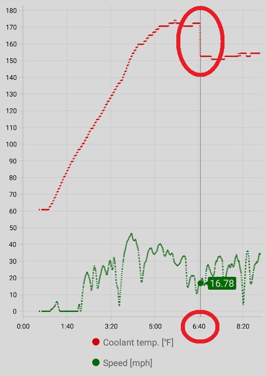
The graph below shows a typical unit in operation, reflecting data I collected from my ODB2 scanner and smartphone.
The engine temperature was approximately 63F when first started. This was also the air temperature outside.
I backed down my driveway and left the car to idle for approximately 1 minute, as I had to run back into the house to grab a couple of things for the road :) [I almost forgot my coffee!]
I then proceeded to leave my development and drive on some 25, 35 and 40 mph roads.
The engine temperature slowly increased until about 172F.
At that point, their was enough heat to transfer over to the AST Smart ECO VCM modules thermal switch and activate the unit.
The ECT1 reported engine temperature dropped by approximately 20 degrees to 152F.
While the engine temperature was being reported below 167F, the ECO mode was disabled.
Their was a small window from 5 minutes to 6:40 where the ECO mode was engaging, however the delayed activation of the AST Smart ECO VCM module is what sets it apart from the competitors - it automatically activates when the engine has warmed up, helping to prevent P0118 and P0128 check engine lights that other, "always on" units experience.

